
IR PC Power On – Quick n’ Dirty

In the living room, a PC running openELEC powers our home theater. The hardware (AMD A6-3500 from 2012…) isn’t anything fancy but its powerful enough to decode pretty much anything thrown at it. Also the Lian-Li PC-C37 case makes it look pretty good in the TV unit. However, the setup has one big disadvantage: No mater the BIOS settings tried, I could not get it to turn on via the infrared remote receiver used. The receiver is a standard Philips eHome compatible receiver as introduced with Windows MCE in 2002. This remote/receiver is probably the best supported one around, works absolutely flawless, but as said would not power on my HTPC.
Lazy as ever, we found different solutions to power the PC on without having to press the actual power button. Fi. by using the Yatse app that supports WoL (Wake up on LAN). This is still an extra step, and could be “streamlined”.
After the thousandth time of standing up and powering on the PC I decided to do something about it! A simple microcontroller and IR receiver should be able to take over my job..
The parts used for this “quick n’ dirty” version are:
- Atmel ATTiny85 Microcontroller (ATTIny25 and 45 do no not have enough ROM for the IRReceiver library)
- TSOP38238 IR Receiver Diode
- 2N2222 NPN Transistor
- A (blue) LED
- Small Prototype Board
- Hook-Up Wire
- Various resistors
Both the micro and TSOP38238 can be bought of ebay for around $1.50 ea, so this project is very feasible for less than $5!
After some trials on a breadboard, the final schematic is as follows:
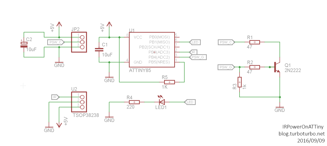
The TSOP38238 is a pretty convenient module and converts the IR pulses into something the micro can use and is compatible the standard IR library available for the Arduino programming environment.
To function the board only requires three inputs (JP2): +5V, PSW_C and GND:
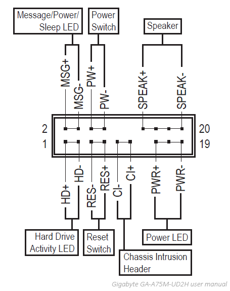
Every ATX motherboard contains a header which contains pins for the LEDs and power and reset switches. My motherboard names the power switch pins PW+ and PW-. To start the PC the PW+ 5V signal needs to be pulled to ground. On the schematic this is referred to as PSW_C, as it is wired to the collector of the 2N2222 transistor. The PW- pin can be used as a general ground, as this is common with the whole motherboard’s ground.
On my Gigabyte GA-A75M-UD2H the header is as follows:
All that is left from the inputs is the 5V signal to power the circuit. Obviously the +5 signal from PW+ cannot be used, the micro draws enough power to pull it to ground. A solution would be to tap into the 5VSB (Standby Power) lead on the ATX header, but this requires cutting and tapping into the ATX cable from the PSU. An easier solution was to use the +5V from an unused USB header, as a BIOS setting allows it to have power even when the PC is turned off.
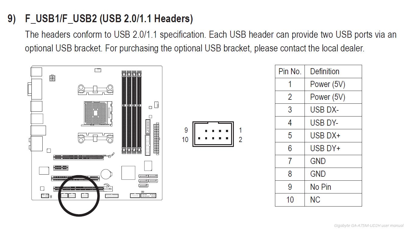
Summarized, the following pins were used:
- PW+ on front panel header as PSW_C
- PW- on front panel header as GND
- Power (5V) on USB Header as +5V
This completes the schematic.
All that is left is the programming, to program an ATTiny from the Arduino environment a couple of items are required:
First of all support for ATTiny micro controllers needs to be added to the Arduino IDE. A good tutorial on how to do this can be found here.
Also a different version of the standard IRRemote library is needed. The ATTiny uses different timer registers compared to the ATMega used in the standard arduino. The library can be downloaded here. Extract the zip file and place it in the arduino/libraries folder. For my code I have renamed the folder from IRremote to tiny_IRremote so I can use both the original library and the ATTiny version.
In this quick n’ dirty version the IR codes are hard coded into the program. The eHome MCE remote sends two alternating commands for PowerToggle, so both are defined as OK.
// Load IR library
#include <tiny_IRremote.h>

// Define IR Hexcodes to match
#define IR_POWERBTN 0x800f840c
#define IR_POWERBTN2 0x800f040c

// Delay between succesfull ir recieves
#define TIMERDELAY 1000

// Power pules
#define PULSETIME 20

// Led pulse time
#define LEDTIME 250

//Pin Assignment
int RECV_PIN = 3;
int SWITCH_PIN = 2;
int LED_PIN = 1;

//Timer
long timer;

//Init IR Reciever
IRrecv IR_Reciever(RECV_PIN);

//Init Decoder and buffer
decode_results IR_Decoder;

void setup()
{
  //Start IR Reciever
  IR_Reciever.enableIRIn();

  //Init Switch Pin
  pinMode(SWITCH_PIN,OUTPUT);
  digitalWrite(SWITCH_PIN,LOW);

  //Init LED Indicator and indicate power on
  pinMode(LED_PIN,OUTPUT);
  for(int i = 0; i<5;i++) {
    digitalWrite(LED_PIN,HIGH);
    delay(50);
    digitalWrite(LED_PIN,LOW);
    delay(50);
  }

  //Init Timer
  timer = 0;
}

void loop() {
  // Reset timer after timeout
  if(timer != 0 && timer + TIMERDELAY < millis()) {
    timer = 0;
  }

  // Check if anything is recieved
  if (IR_Reciever.decode(&IR_Decoder)) {
    IR_Reciever.resume();  // Continue recieving

    // Match code if timer is reset
    if(timer == 0 && (IR_Decoder.value == IR_POWERBTN || IR_Decoder.value == IR_POWERBTN2)){
      // Flash LED and pull switch pin
      timer = millis();
      digitalWrite(LED_PIN,HIGH);
      digitalWrite(SWITCH_PIN,HIGH);
      delay(PULSETIME);
      digitalWrite(SWITCH_PIN,LOW);
      delay(LEDTIME);
      digitalWrite(LED_PIN,LOW);
    } else {
    }
  }
}
To program the ATTiny a SparkFun Pocket AVR Programmer was used. However, the link mentioned above on how to add support for the ATTiny lists a few alternatives. For instance, a regular Arduino can be used for this as well.
Now the board can be connected to the PC! To achieve this I’ve soldered some jumper wires connecting PW+ and PW- in parallel with the power switch. This keeps the power switch functional. +5V power was connected directly from the USB header. Some insulation was added with electrical tape.
The results have been great, the circuit is reliable and reception is very good! Haven’t needed to get off the couch so far..

As this is a very quick n’ dirty solution to a laziness problem a couple of issues might exist with this schematic/program:
- No input protection to the ATTiny
- No reverse voltage protection
- IR Codes are hard coded, any changes involve reprogramming of the microcontroller.
These issues might be resolved in a not so quick and dirty solution in the future.